Week 3.
Electronics and programming This week is dedicated for r catch up plans and be back on track by Friday.Coming Week Luciano is coming to Trivandrum and he will be guiding us to integrate all skill we acquired during last the first three week and make our final project. According to Franc Electronics and programming is NOT a one step learning process. It is a permanent learning process. Depth is infinite.Day 1
Electronics Production
Today we were discussing about SMD Soldering and tips to make smd soldering easy , neat and clean. After we have to solder FAB ISP Which is our Assignment.Franc happened to see a heat gun kept hot after using. So he started with educating us about the proper use of the heat gun. He told us to remember to put it in cold air after use until no heat comes out.Otherwise it wil harm the device. According to Franc soldering SMD components is not like painting. First we need to place the component using a Tweezer then we need to bring Soldering Iron in then Solder in then Solder out and after that Soldering Iron out. Using the double side tape will help to fix the board to the table, so that we can solder without minding the movement of board. Always we should start with the microcontroller or the central component then continue towards the perimeter. We must not give heavy pressure to the tweezers. If we do so that may be the last timewe are seeing the component. According to Franc it is better to avoid coffee on the soldering day which will help in reducing the had shiver :). We must ensure proper lighting and its a good practice to use eye loupes while soldering.
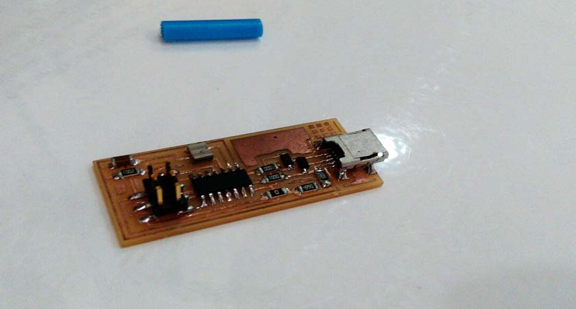
Assignment Me and Vishnu was in one team. We prepare the Roland Modela bed and sacrificial layer and after that download desin files from here and using fab modules milled the board. After milling together we finished soldering. Now we had to program the board to make it work as an ISP. Instruction to programming and debugging can be found here .
Process FAB ISP
We followed all instructions in the above link and completed programming our ISP Sucessfully.
Programming the fabisp
First we need to install avr utilities and avrdude (Version 6.1). Type the following commands in terminal for that,
sudo apt-get install gcc-avr binutils-avr gdb-avr avr-libc avrdude

sudo add-apt-repository ppa:pmjdebruijn/avrdude-release

sudo apt-get update

sudo apt-get install avrdude
Now connect the isp to Atmel Programmer and power it using mini usb cable.Now we have to download the firmware fro here. After unzipping the folder, open the folder and right click to select open terminal here.Then type following in terminal.
make clean
make hex
Now open the make file using notepad and replace line
#AVRDUDE = avrdude -c avrisp2 -P usb -p $(DEVICE)
by
AVRDUDE = avrdude -c atmelice_isp -P usb -p $(DEVICE)
Save the file and come back to terminal and enter the following commands to load the firmware to the ISP.
make  fuse
make program
Completed FAB ISP
Now the ISP is ready, all we have to do now is just remove the SJ1 solder jumper by desoldering it.
Download all files here .
Day 2
Electronics Basics
Today we learned the basics of electronics circuits. Franc gave us a brief about the components that we use for electronics circuits like resisitors, capacitors, switchs, potentiometers etc. Also Franc gave us a brief lecture on basics about microcontrollers, registers, Fuses (HIGH, LOW, EXTENDED), Interrupts, ADCetc.
Capacitors
The capacitor is a component which has the ability or “capacity” to store energy in the form of an electrical charge producing a potential difference (Static Voltage) across its plates, much like a small rechargeable battery.
Resisitors
Resistor Basics. Resistors are electronic components which have a specific, never-changing electrical resistance. The resistor's resistance limits the flow of electrons through a circuit.
Switch
In electrical engineering, a switch is an electrical component that can break an electrical circuit, interrupting the current or diverting it from one conductor to another.
Diodes
A diode is an electrical device allowing current to move through it in one direction with far greater ease than in the other. The most common kind of diode in modern circuit design is the semiconductor diode, although other diode technologies exist.
Potentiometers
A potentiometer is a simple knob that provides a variable resistance.
Transistor
A transistor is a semiconductor device used to amplify or switch electronic signals and electrical power. It is composed of semiconductor material with at least three terminals for connection to an external circuit.
Microcontrollers
A microcontroller is a small and low-cost computer built for the purpose of dealing with specific tasks, such as displaying information in a microwave LED or receiving information from a television’s remote control. Microcontrollers are mainly used in products that require a degree of control to be exerted by the user. Microprocessors are used to execute big and generic applications, while a microcontroller will only be used to execute a single task within one application. Some of the benefits of microcontrollers include the following:
Fuses in Microcontrollers
Fuses essentially configuration parameters, or like the chip's BIOS.They control things like which oscillator to use, and what speed to run at (ie. the internal 8MHz oscillator, or an external crystal), brownout detection, and the size of the boot flash.
Registers in Microcontrollers
Register is a main part in the microcontrollers and processors that provide a fast way to collect and store data. If we want to manipulate data with a controller or processor by performing addition, subtraction, and so on, we cannot do that directly in the memory, but it needs registers to process and store the data. Microcontrollers contain several types of registers that can be classified according to their content or instructions that operate in them.
Interrupts in Microcontrollers
The interrupts refer to a notification, communicated to the controller, by a hardware device or software, on receipt of which controller momentarily stops and responds to the interrupt. Whenever an interrupt occurs the controller completes the execution of the current instruction and starts the execution of an Interrupt Service Routine (ISR) or Interrupt Handler.
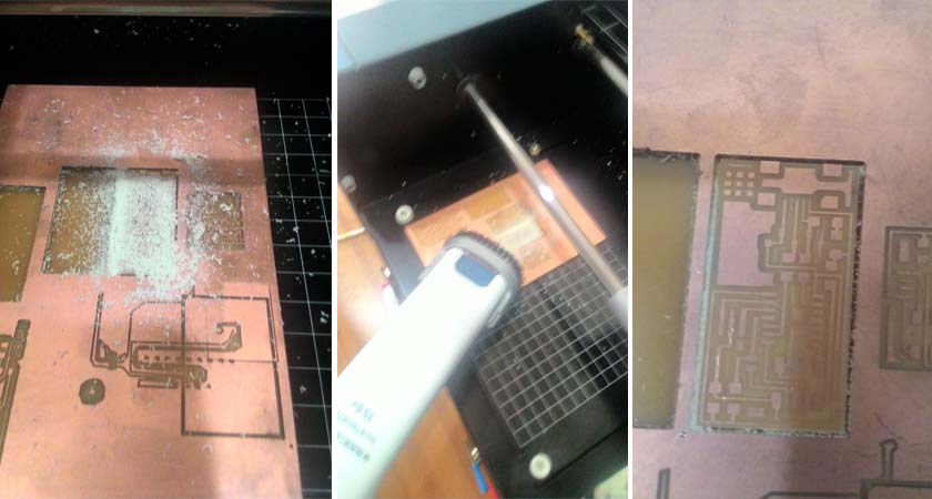
After these it was time to mill and solder separate fab isp. Since availability of mini USB Cables was less i decided to go with Andy Bardagjy's design the FabISPkey. This can be directly connected to USB Ports. I downloaded all required files frm Francs archive.
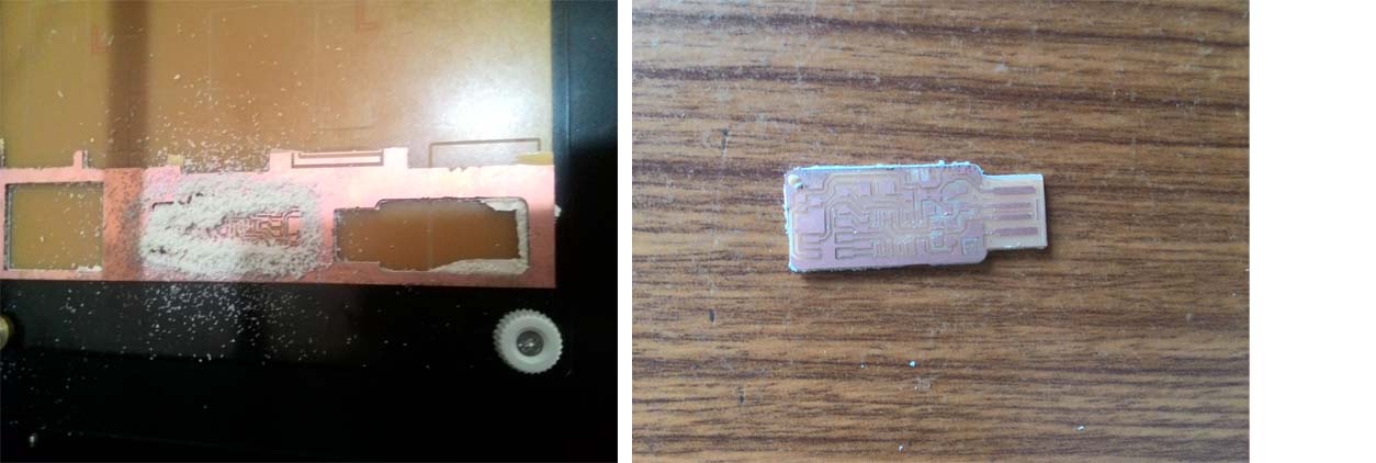
FAB ISP Key Process
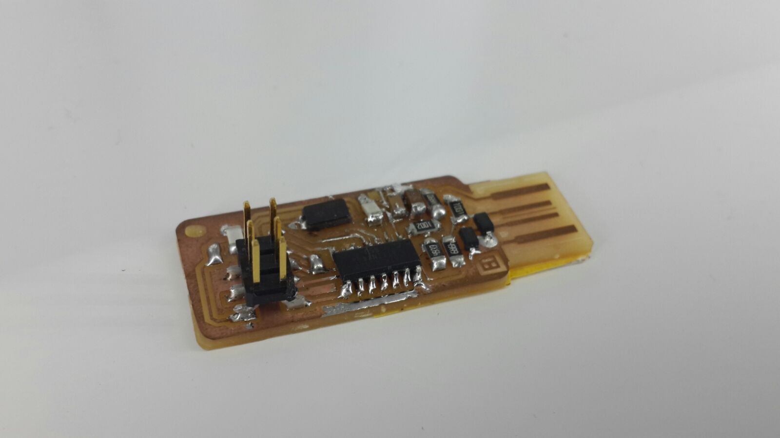
Completed FAB ISP Key
I uses a double sided sticker without removing one end on the back of FAB ISP Key,so that it will be fit on USB Ports without any loose contact. Programming is smae as that of Neil's Version of Fab ISP since all the component and configuration used in FAB ISP Key is same. So just follow the instructions given in Day 2.
Day 3
Electronics Design usuing Kokopelli
Today Franc gave us a crash course in Kokopelli. Its an amazing software for designing circuits. I am used to Proteus and Orcard, but this is the first time using codig for creating PCB and circuit designing. Today we have to download the Hello World Board Cad file and we need to edit the same using Kokopelli to add an LED connected to Pin 8 and a Switch connected to Pin 7.
This is how to add a Led to the board
led=LED_1206('led')
# adding LED with label led
pcb=led.add(pcb,XTAL1.x,IC1.pad[5].y,z,180)
#Adding LED to PCB and giving x and y position according to other components position.
Code for making connections between components.
pcb = wire(pcb,w,led.pad[1],IC1.pad[5])
#this will connect pad 1 of LED and pad 5 of IC
Assignment: Add an LED and a button to Hello World board
Hello World Board Modified cad file.
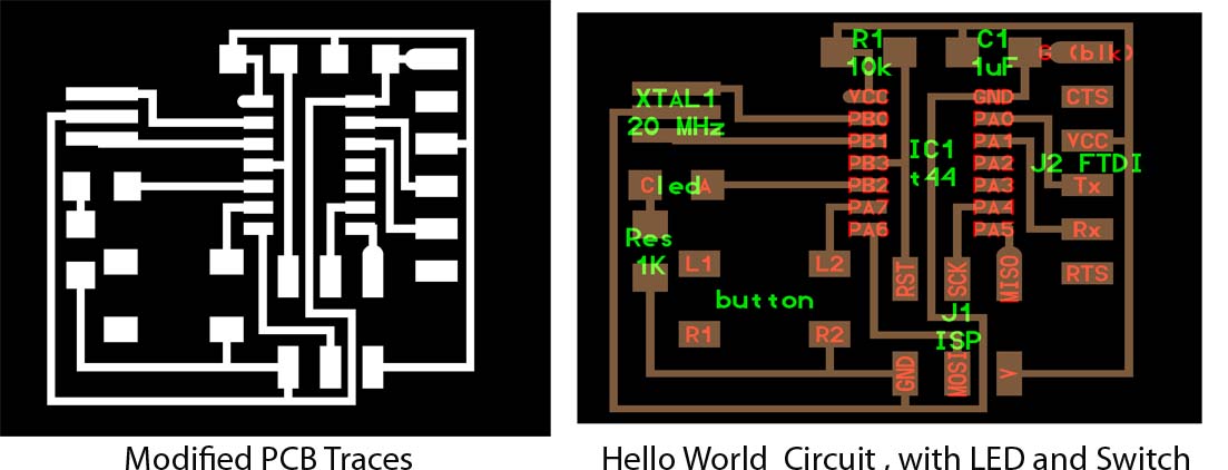
Hello world Modified Circuit
Now we have to mill the circuit using Modella and solder the components.I had to wait in the queue for milling the pcb since there were peoples who completed pcb designing before me. It is almost 5pm when I got chance to mill the board. Completed milling in 15 mins and now its time to solder components. Now its very easy to solder after collecting components. I finished soldering within 15 mins.
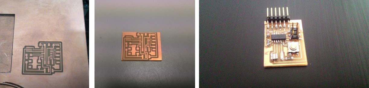
Hello world Milled and soldered Circuit
Day 4
Embedded Programming
Today we learned about embedded programming. Embedded systems programming is the programming of an embedded system in some device using the permitted programming interfaces provided by that system.Franc explained us about different levels of programming language like High level languages, Mid Level Languages (C, C++), Low level languages (Assembly language). C is the most widely used language in programming.C remains a very popular language for micro-controller developers due to the code efficiency and reduced overhead and development time. C offers low-level control and is considered more readable than assembly.
Now franc gave us a brief idea about programming and he told us to add author, date, description and license information on the top of the code. He also suggested to comment code, so that later someone (even for us later) looking at our code can easily understand what is what. If we can program in assembly level it will allow us to have more freedom over the control of the device. Attiny 44 have 4k of memory and if we use Arduino IDE to program the Sketch libraries consume around 50 % of program memory and we have only remaining 50 % percent for our use. This is where Assembly level programming have advantage.
Programming Hello FTDI
We have our hello world board milled and soldered ready for program. we need to understand the pinout of ATTiny 44A for programming the board without any confusion.
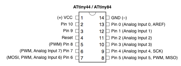
Pinout of ATTiny 44 A
Inorder to program this we need our FAB ISP, a mini USB Cable , FTDI header cable and our hello world circuit.Now we have to connect the ISP to our laptop using the mini USB Cable and then connect the hello world board to our ISP (beware of orientation). Now start Arduino as root (sudo ./arduino @ terminal will do). Now make sure that we have ATTiny libraries added(Explained in week 1 Documentation). Also make sure that in Tools Menu we have selected Board as "ATTiny" and Processor as "Attiny 44 "and programmer as "usbtinyisp".
Now we were about to load blink program to the board, but i selected the fade program from the examples.Its pretty easy to burn program to the board, all we have to do is set the led pin as pin 8 (that is where we have connected LED in the board) and compile the program and just click upload.
/*
 Fade

 */

int led = 8;           // the pin that the LED is attached to
int brightness = 0;    // how bright the LED is
int fadeAmount = 5;    // how many points to fade the LED by

// the setup routine runs once when you press reset:
void setup() {
  // declare pin 8 to be an output:
  pinMode(led, OUTPUT);
}

// the loop routine runs over and over again forever:
void loop() {
  // set the brightness of pin 8:
  analogWrite(led, brightness);

  // change the brightness for next time through the loop:
  brightness = brightness + fadeAmount;

  // reverse the direction of the fading at the ends of the fade:
  if (brightness == 0 || brightness == 255) {
    fadeAmount = -fadeAmount ;
  }
  // wait for 30 milliseconds to see the dimming effect
  delay(30);
}
Videp of Fade Led in Hello World Board
Serial communication (send something to computer, read something from computer)
In serial communication we use FTDI header to communicate with our Computer. The FTDI header have 6 Pins and the other end is USB with which we connect it to our Laptop.
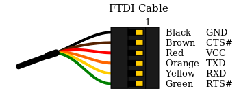
FTDI Header
Generally we use SoftwareSerial headers for serial communication. So wee need to include the library in our program to enable serial communication. We wrote a program for turning on LED connected to pin 8 when we send character "c" from Laptop and send character "e" back when we press the button on the board.
The program
#include

const byte rxpin =0;
const byte txpin=1;


//set up a new serial
SoftwareSerial mySerial (rxpin, txpin);
void setup() {
  pinMode(8, OUTPUT);
  pinMode(7,INPUT);
  digitalWrite(7,HIGH);
  mySerial.begin(9600);
  }


  void loop() {

    //reading serial chara
    if (mySerial.read()=='c')
{
  digitalWrite(8, HIGH);
  delay(1000);
  digitalWrite(8, LOW);

  }
  else {}

  //reading reset press and serial printing

  if (digitalRead(7)==LOW){


    mySerial.print('e');
    }
  else {}

  }
Now we connect the board to FAB ISP and coonect FTDI header to board and conncet the other end to Laptop. Now we have to burn the above program to the board using arduino ide. After burning the program to board and onece it is completed successfully we need to open the Serial monitor window and press the button in the board.
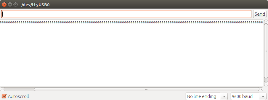
Serial Monitor Window after pressing button
When we send "c" using serial monitor the LED will glow. Thus we completed the serial communication via FTDI Header.